
You see, kids, building an FPGA-based network filter isn’t just about blocking packets; it’s all about the design. In this blog, I’ll take you through how I created, tested, and re-tested the implementation of an Ethernet filtering system—laying the first stone of something LEGENDARY.

Never seen How I Met Your Mother? Doesn’t matter. If you love cybersecurity, FPGA development, and building network defenses, this one’s for you.
Why use an FPGA for Ethernet filtering?
Software-based packet filtering (firewalls, deep packet inspection, etc.) can be overwhelmed under heavy loads of data, creating lag and slowing things down. That’s where FPGA-based Ethernet filters comes in to save day! They’re built for speed and efficiency, handling data with near-zero latency. FPGAs can process multiple packets at the same time, eliminating the bottlenecks of traditional processing. In short, they do the heavy lifting so the network stays fast and secure. That’s why ,automotive industry, aerospace, military and telecommunication companies use them.
The Journey..so far
I started tinkering with FPGAs using a different model in another blog, but my ambitions have grown. I have a huge project in mind, so I needed a board that could handle the crazy tasks I have planned (stay tuned to learn more)! Let me introduce you to the Arty A7 100T FPGA board, developed by Digilent. It’s a good platform for enthusiasts like me who want to dive into the world of Field Programmable Gate Arrays (FPGAs). You can find more information about this board here. For programming the Arty A7, I used Vivado. Now, when you first use it, will be a little bit overwhelming (I am being generous here) for noobs like myself. However, if you take the time to find some videos and do some research, you will find your way around it. So, don’t be discouraged, it is a learning experience after all!
New Board… New LED Patterns
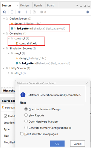
Fist I downloaded the Arty-A7-100 Master constraint file. Remember, a constraint file in FPGA development is used to specify the physical and timing requirements for the design, such as pin assignments, clock constraints, and input/output standards. Next, I created the VHDL code that will make the LED lights on the board to turn on and behave in a pattern when I turn on a switch on the board.
Once I have both files in Vivado, we can proceed with the following:
- Synthesis: This step turns the VHDL code into a circuit design
- Implementation: During this phase, the logic is mapped onto the FPGA’s resources.
- Generating the Bitstream: The final step involves creating a bitstream file that can be uploaded to the FPGA to configure it with the programmed design.
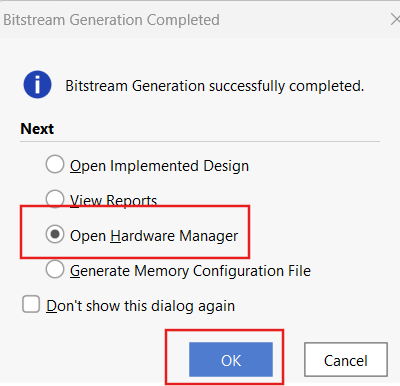
Now! It’s time to move the Bitstream to the Hardware, first I select “Open Hardware Manager.”
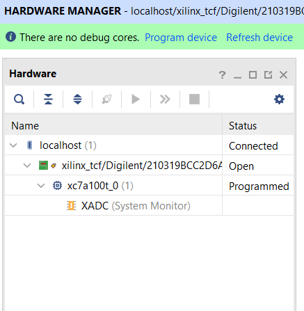
If there is an issue with the FPGA board not being detected just click on “Open Target” and select “Auto Connect” Once the board is detected, you should have a screen that looks like this:
Now, I clicked “Program Device” make sure you select the “.bit” file generated earlier.
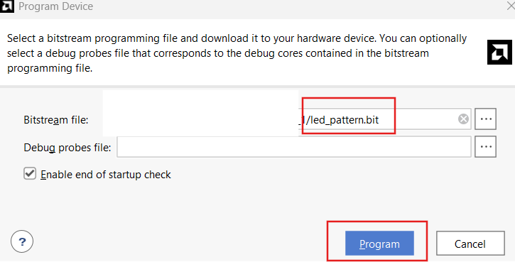
After these steps are done (without failing 😂) the FPGA will be ready to execute the design, in this case, making the LED lights display the desired pattern.

Suit Up for Secure Packets
Now, an FPGA-based Ethernet filter operates by analyzing incoming packets at the hardware level, using rules to determine whether to allow or block traffic.
I spent a week and half of trying to set up the block designs and pairing all the FPGA components within Vivado. I got an error that said I had 774 I/O unused and a gazillion of other errors that just made me lose sleep for 2 nights. I needed to understand why this was so difficult. So I thought, if I could get the board to program without the block design before, why not try what I know works?

I ditched the block design (for now) and went deep into VHDL coding to implement packet inspection. The idea is simple—capture incoming Ethernet data frames, analyze them, and decide whether to block or allow based on rules. Sounds easy, right? Wrong.
After a lot of research, I found out that I need the following VHDL files.
- Ethernet_RX.vhd – This module is responsible for receiving Ethernet data frames, processing the incoming data and sending the frame alongside with a signal to indicate if the data is valid or not.
- Ethernet_TX.vhd – This module transmits the Ethernet data frames by processing the outgoing data and sending it over the Media Independent Interface (MII). The MII standard connects the medium access control (MAC) to the Physical layer (PHY) chip.
- Ethernet_Filter.vhd – The filter module is responsible of …well…filtering. Here it is determined if the Ethernet data frames are to be allowed or blocked based on the destination MAC address.
- Ethernet_Top.vhd – This is where the magic happens! This module integrates all the other components -receiver, filter, and transmitter—into a complete process. It also manages the clock and reset signals, ensuring data flow throughout the design goes well.
- How do I know if this works? Here comes the Test Bench! Ethernet_TB.vhd This module simulates Ethernet data, and verifies that the receiver, filter, and transmitter work as intended. It generates test signals, monitors responses, and helps debug and validate the entire system.
HA! I don’t need to program the board just to see if it works!
Wait for It… Testing the Design in Vivado!
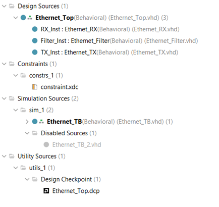
Now that I have all the modules written and the constraint file done, I need to move over to Vivado and see if it works! As seen in the picture below, I have my receiver, filter, transmitter, top module, constraint file and test bench all ready to go in Vivado.
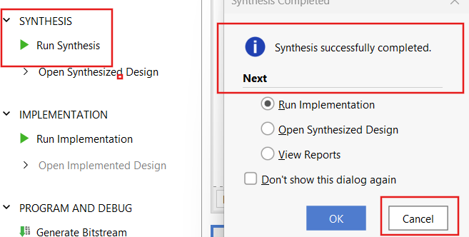
Next, I need to “Run Synthesis” and once “Synthesis successfully completed” appears, select “OK”.
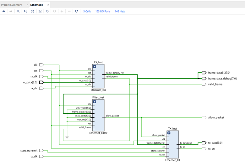
Great! Now I can go to the “RTL Analysis” section and click on “Open Elaborated Design” and see how the modules connect.
Got the implementation working and now I can see the Device, the Power Analysis and Timing information and other useful information about my board and the design.
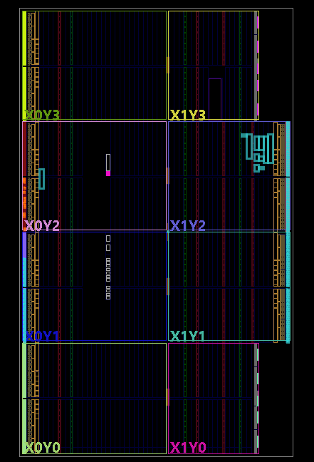
Device
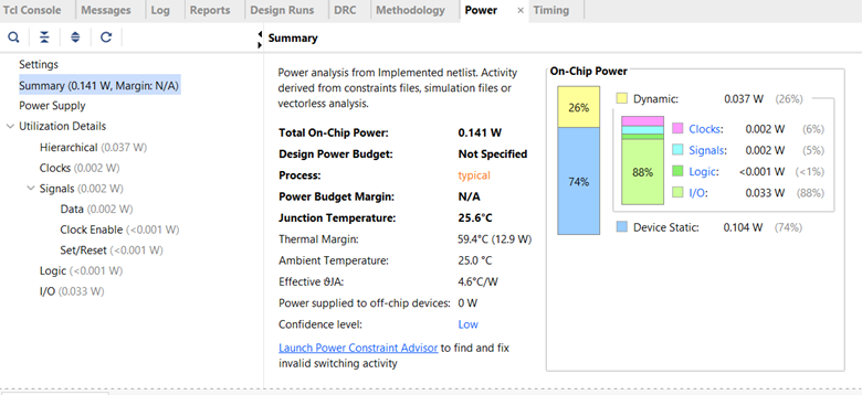
Power Analysis
Alright… the moment of truth! Now I navigate to “Simulation” and select “Run Behavioral Simulation”.
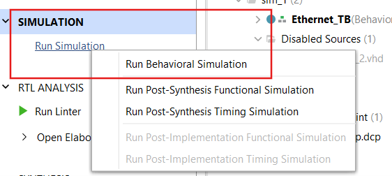

This will take some time but once is completed, I got this screen.
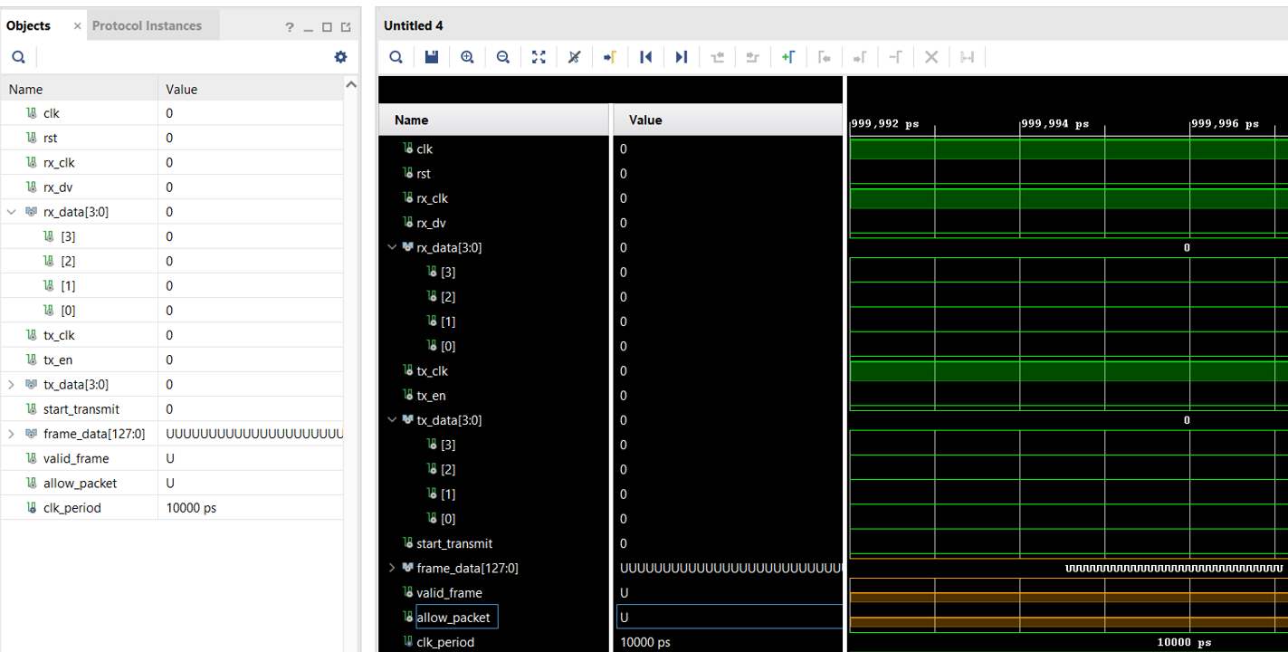
So in theory the simulation worked.. the code.. not so much! You see all those “U” in the image above? Well, that stands for uninitialized. Which means that the modules weren’t able to process the Ethernet data frames and the filter did not know what to do.

So, there I was, staring at a simulation full of ‘UUUU’ values like they were waiting for me to do something about it besides crying. But then I realized that I had come so far—from LED patterns to full-on Ethernet filtering. Now I go back, check my test bench, ensure my signals are initialized, verified the data flow and and who knows what other rabbit holes I’ll fall into.
What’s Next?
This is just the beginning. I got the implementation working, but the simulation didn’t (yet!). The next challenge? Debugging and testing—deploying my filter onto an actual network. And who knows? Maybe I’ll find ways to bypass my own filter 😈.
That’s how cybersecurity works, right? You build, you break, and you build again.

Stay tuned! Until Next time- Izzny💜